Air Gaging in a Quality Management System
In the quality world, air gaging ranks with micrometers, calipers, comparators, scales, CMMs and many other instruments in that they are all considered measurement and test equipment (M&TE).

In the quality world, air gaging ranks with micrometers, calipers, comparators, scales, CMMs and many other instruments in that they are all considered measurement and test equipment (M&TE).
Under quality standards such as ISO 9000, ISO 13485, AS9100 and IATF 16949A, a complete air gaging program will be comprised of not only the physical components that make up the gage but also the maintenance and calibration programs necessary to keep those components in an accurate operating state.
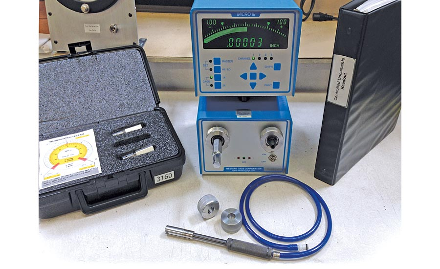
The basic components of any air gage system include the air gage, setting master(s) and electronic/pneumatic readout. Each one of these components will require periodic calibration by in-house personnel or by an outside laboratory, both of which must meet the quality system’s requirements.
What constitutes calibration, who can calibrate it and how often so that the quality system requirements are met?
Before diving into these questions, the plurality of terminology in the air gaging industry must be cleared up. There are multiple terms that mean the same thing—conversely there are terms that mean the same thing but the use of one may be more appropriate in a given context. The sidebar lists terms and their synonyms that are commonly used.
The most important consideration of an air gage operating in a quality management system is the assurance of accuracy through calibration.
A strict definition of the word “calibration” held by most quality systems will read something like: “the relationship between values of an instrument and the corresponding values realized by standards.” For an air gage to meet that definition, insight into the air gage operation will be of value.
Air Gaging Terms To Know
- Air Gage: air probe, air spindle, air plug, air ring, tooling, air mic, member
- Setting Master: setting ring, setting plug, set disc, master ring, master plug, master artifact, reference standard
- Display Instrument: readout, column, amplifier, comparator, tower, meter, display, air/electronic converter
- Calibration Certificate: calibration report, long form cert
- Range: span, spread, pre-set, tolerance
- Gain: scale factor, scaling, sensitivity, magnification
- Setting Gain: mastering, scaling, spanning, setting spread, setting sensitivity, teach, qualify
- Bias: zero offset
- Biasing: zeroing
- Magnification Kit: orifice set, flow restrictors
Air Gages and Their Operation
Air gages are a comparative type of measurement device. They operate in a two system world: single master and dual master systems, where each requires the use of one or two setting masters respectively, to either set the zero offset or to set the gain. The term “calibration” has been used very loosely to describe these two operations.
A strict adherence to the definition of the term calibrate would require several basic calibration program elements to carry out an air gage “calibration.” The ISO/IEC 17025 standard is one of the most referenced calibration standards for the general requirements of a competent calibration lab. The elements in this standard should be employed in any operation performing calibration on in-house M&TE. The key elements are:
- A calibration procedure
- A certificate of calibration, or some other simplified form of recording the results including as-received and as-calibrated conditions.
- Established acceptance limits and a procedure on what to do in the event the as-received calibration is out
- of tolerance
- An estimate of the uncertainty of measurement and a statement of such on the report
- Traceability of the reference standards to the International System (SI) of units.
- A method to evaluate the trend of the calibrations and the interval between calibrations.
- A means of identifying that the instrument is calibrated and its calibration due date
Dual Master Air Gage
The dual master air gage system is considered a “calibrate at time of use” gage. A calibration on a dual master system can be performed when all the elements listed above are in place. When the above elements are not in place, the more appropriate term for describing the steps involved with using a dual master gage is “mastering,” not “calibrating.” Mastering is simply applying two reference standards to set the gain. Mastering should be performed periodically to adjust for environmental effects or as an intermediate check between calibrations. However, when a new gage is set up or a significant interval of time has passed, “calibration” of the dual master gage is called for.
Dual master systems can be calibrated with the two masters that are typically ordered with it. However, calibrating with the same two reference standards that were used to “master” the instrument has its drawbacks. Under certain conditions, scaling errors can be masked. In addition, a two point calibration does not reveal linearity errors which can be significant in wide range measurements. To really know if your gage is accurate, a third data point is necessary.
Single Master Air Gage
The single master system has similar calibration requirements. But again, without the elements of a quality system, the operation is better termed “mastering” the gage, not calibrating it.
Understanding the single master beast will aid in knowing how to calibrate it. Single master air gage members are manufactured to a standardized pneumatic gain, likewise the readout is set to a standardized electronic gain, as opposed to being scaled for each individual, and “different,” air gage member. The standardization allows for interchangeability of single master air gages. Meaning a single master air gage member can be used with any single master readout, and vice versa, without having to reset the gain on the readout. Single master readouts have the gain locked into them at the factory so that operation in the field only requires one setting master—used to zero the instrument.
Readouts
Single-master readouts are best calibrated independent of the air gage member (tooling). Calibration is performed with flow restrictors that simulate the “standardized” tooling. The flow restrictors (orifice sets) come in sets of three. Two orifices are used for mastering (scaling) of the readout while all three are utilized for calibration. The orifice sets themselves are calibrated with traceable reference standards—meeting the quality requirements of traceability. Orifice sets can be purchased and used by the end user but are more commonly used by the manufacturer in the factory.
Air Gage Member
The gaging member (tooling) of a single-master system also requires calibration. This ensures that the entire system, meaning the readout and the tooling, is operating accurately. Use of the one master which is typically purchased with the single-master tooling is appropriate for “mastering” (“zeroing”) the instrument and this should be done periodically to account for environmental changes. However, using just that one master for a single point calibration is insufficient. At a minimum a second master which provides a second data point should be used.
A single data point calibration checks that the zero offset is set correctly; two data points enables a measure of the zero offset and gain; three data points evaluates the zero offset, gain and linearity. The more data points, the better the calibration. However too many points eventually adds no more value and increases the cost.
A good rule of thumb for the number of data points needed as a minimum to calibrate an air gage is: one reference master above the system type. So a single master system would require two setting masters and a dual master system would require three setting masters. This minimizes the cost of the masters and provides an acceptable level of confidence in the calibration.
Setting Masters
Setting masters are the reference standards used for the calibration of air gage systems—typically rings, plugs and set discs conforming to ASNI/ASME specifications. Setting masters undergo the same rigors demanded by the quality system as air gages. The setting master calibration certificate number is referenced on the air gage calibration certificate to fulfill the traceability to a National Measuring Institute (NMI), e.g. NIST, requirement.
Air gage calibration acceptance limits are set based on the product tolerance, or alternatively on the manufacturer’s gage specifications. When based on the product tolerance, a 10% or less acceptance limit should be used; 5% is a better number. A .002” product tolerance would translate to a .0002” calibration acceptance limit—and the accuracy of the masters used to calibrate the gage should be 10% or less of that, or .00002”. When manufacturer’s specifications are used, the acceptance limit for calibration should be less than or equal to the manufacturer’s accuracy specification.
Accuracy of an air gage will be diminished if there is any buildup of oil and grime at the jets and air vents. Good calibration practice will take note of this when recording the as-received condition. Cleaning procedures or a maintenance plan should be in place to keep the gage clean. Readouts will tend to be mostly affected by oil contamination inside the air lines, pneumatic components and on printed circuit boards. A good air filtration and coalescing system is a must to keep your gage in top shape. Tooling wear should be monitored. Since the air gage nozzle is recessed, wear does not directly affect the accuracy of the measurement; however excessive wear will result in increased clearance causing imbalance and poor repeatability. Repeatability and drift errors are best uncovered by a GR&R study. Calibration may not detect repeatability and drift errors.
The calibration interval of an air gage is established by the user and will be dependent on the application, usage and environment. Every six months or every year is a good starting point. The interval should be adjusted by evaluating the results of past calibrations. Too many as-received failures dictate shortening the interval. The interval can also be lengthened if a consistent passing trend is observed.
Your air gage supplier should be able to assist you with your air gaging maintenance and calibration needs. Ensure that the laboratory that you use is ISO/IEC 17025 accredited or meets the requirements of the standard. Accredited labs will have a document called “scope of accreditation” which lists their calibration services. This document is registered with their accreditation body and is usually available on the manufacturer’s website. Check their scope to verify that air gaging is part of their accredited calibration services.

